RESEARCH ARTICLE
The Research on Influence of Unloading on Borehole Stability in Clay-Rich Shale Formation
Yi Ding, Xiangjun Liu*, Pingya Luo, Lixi Liang
Article Information
Identifiers and Pagination:
Year: 2017Volume: 10
First Page: 204
Last Page: 219
Publisher Id: TOPEJ-10-204
DOI: 10.2174/1874834101710010204
Article History:
Received Date: 29/04/2017Revision Received Date: 01/07/2017
Acceptance Date: 30/08/2017
Electronic publication date: 16/10/2017
Collection year: 2017
open-access license: This is an open access article distributed under the terms of the Creative Commons Attribution 4.0 International Public License (CC-BY 4.0), a copy of which is available at: https://creativecommons.org/licenses/by/4.0/legalcode. This license permits unrestricted use, distribution, and reproduction in any medium, provided the original author and source are credited.
Abstract
Introduction:
Unloading phenomenon happens in the beginning of drilling and is able to change stress state around borehole. This change of stress state causes impact on rock structure and strength, thus affecting the evaluation of wellbore stability. Especially for determining initial mud pressure, unloading is a significant influence factor. Clay-rich shale formation is well-known for high risk of borehole collapsing, appropriate mud pressure is necessary to stabilize wellbore. Therefore, the unloading influence needs to be considered when it comes to selection of initial mud pressure.
Materials and Methods:
In this paper, based on the triaxial test, unloading situation has been simulated to investigate the influence of unloading on rock mechanical property. It is shown that clay-shale strength declines with increasing unloading range. Also, note that in comparison with internal friction angle, cohesion has larger decline caused by unloading.
Results:
Taking account of the unloading influence, new model has been established to investigate wellbore stability. These results demonstrate that unloading creates variable strength decrease at the wall of borehole due to different in-situ stress and well trajectory. This strength decrease gives rise to increasing collapse pressure. In particular, unloading has relatively larger impact in the formation with strong anisotropy and high in-situ stress. Besides, inappropriate well trajectory will increase unloading impact.
Conclusion:
Finally, this model has been applied to several cases in clay-shale formation, Northern China. And the new model in each case is well consistent with oilfield experience, indicating its practicability and proving unloading is a non-negligible factor for the assessment of wellbore stability.
1. INTRODUCTION
Wellbore instability is a complicated issue and affected by numerous factors, including pore pressure, in situ stress, drilling fluid, well trajectory, and so on [1]. In clay-rich shale formation, wellbore collapse is a common problem of increasing cost and delaying the drilling process. In order to avoid wellbore collapse, the direct method is to have appropriate mud pressure. In particular, strong hydration of clay-rich shale makes collapse pressure variable with drilling time. It is thus necessary to adjust mud pressure precisely for keeping wellbore stability in the whole drilling operation [2]. Considering this hydration of clay-rich shale, numerous studies have conducted the optimization of drilling fluid to restrict hydration and also developed kinds of mechanical models to choose suitable mud pressure with drilling time [3-4].
With regard to determination of mud pressure, the initial value is vital, but is also very tricky to be obtained accurately. If the initial drilling density is too low, borehole collapses and shape of borehole tends to be anomalous. In anomalous borehole condition, common mechanical model is not applicable for evaluating wellbore stability, increasing the difficulty of stabilizing wellbore [5]. On the other hand, if the initial drilling density is too high, it is not facilitated for increasing drilling rate, leading to long drilling time. Since clay-rich shale has strong hydration, long drilling time boosts the risk of borehole collapsing in the late stage of drilling operation.
In the beginning of drilling, drilling fluid just starts contacting with rock, barely causing hydration on rock around wellbore. Hydration is thus not important influence factor of choosing initial mud pressure. However, once a well is drilled, the rock in the borehole is replaced by drilling fluid. As a result, the stress state has been modified near the borehole wall, leading to the change of rock strength. It is clear that this strength change will cause variation of collapse pressure in the initial stage of drilling. The researches on the influence of unloading on rock strength demonstrate that these unloading parameters, like unloading range, rate and path are closely related to rock mechanical parameters [6]. Additionally, Zhang et al. [7] suggested that new constituent equation of rock needs to be proposed for rock in unloading condition. Even though the previous researches have proved the influence of unloading on rock strength, it is rarely applied to analyze wellbore stability in petroleum engineering.
Therefore, in this paper, triaxial test was applied to simulate unloading condition and analyzed the influence of unloading on clay-rich shale mechanical property. Based on the experimental results, new model considering unloading influence was established to investigate wellbore stability. The aim is to provide a more precise method of determining initial mud pressure, and develop a good foundation for wellbore stability in the late stage. The application shows this model is close agreement with oilfield experiment, proving its practicability.
2. THE PROPERTY OF CLAY-RICH SHALE
Clay-rich shale was taken from North China Dongying formation, shown as Fig. (1). Scanning electron microscope was conducted to observe the microstructure characteristic of clay-rich shale, shown as Fig. (1b). The result shows micro-cracks and micro-pore is predominant, which apparently contribute a lot to drilling fluid invasion.
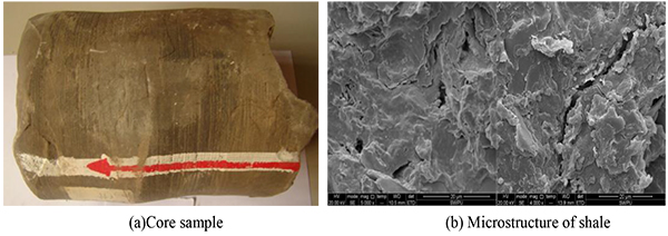 |
Fig. (1). Shale rock structure. |
XRD analysis results are presented in Tables (1 and 2). In those samples, clay mineral is predominated and its average content is 60.95%. In clay mineral, illite is the main content and averages 56.55%. Montmorillonite is extremely little and only averages 0.01%. Whereas, the illite smectite has high content. It is noted that content of clay mineral is abundant. Even though the Montmorillonite with strong hydration are in low content, illite smectite is rich, which indicate strong hydration of clay-rich shale.
| Sample | Mineral Composition(%) | |||||
|---|---|---|---|---|---|---|
| Clay Mineral | Pyrite | Quartz | Plagioclase | Calcite | Dolomite | |
| 1 | 67.52 | 2.51 | 4.45 | 3.82 | 17.50 | 4.20 |
| 2 | 58.63 | 1.80 | 13.90 | 2.11 | 20.01 | 3.55 |
| 3 | 62.28 | 1.91 | 10.15 | 2.01 | 17.92 | 5.73 |
| 4 | 55.41 | 2.13 | 17.36 | 2.92 | 18.73 | 3.45 |
| Sample | Clay Mineral Content(%) | ||||
|---|---|---|---|---|---|
| Illite | Montmorillonite | Illite Smectite |
Kaolinite | Chlorite | |
| 1 | 65.29 | 0.02 | 26.02 | 0.02 | 5.86 |
| 2 | 58.69 | 0.01 | 32.48 | 0.01 | 9.21 |
| 3 | 42.02 | 0.02 | 44.44 | 0.01 | 11.12 |
| 4 | 60.19 | 0.01 | 34.75 | 0.02 | 5.03 |
Wellbore stability analysis is based on rock mechanical property. To achieve the influence of unloading on clay-rich shale strength, firstly triaxial test is applied to obtain clay-rich shale mechanical property in conventional condition, shown as Figs. (2-4). It can be seen that (1) the shape of stress-strain curves in different confining stress is similar, but the strain is small in high confining stress condition. This is because that confining stress offers lateral bracing and imposes restrain on rock deformation. (2) This lateral bracing is able to enhance rock strength, and triaxial compressive strength increases with rising confining stress, showing clear linear correlation. (3) Core samples after failure illustrate that in different confining stress, failure mode of clay-rich shale has no obvious change and still is single shear failure mode, which is slipping break along with one failure plane.
 |
Fig. (2). Stress-strain curves in different confining stress. |
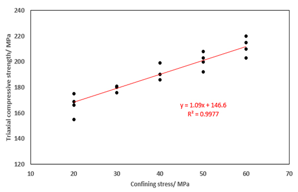 |
Fig. (3). Compressive strength in different confining stress. |
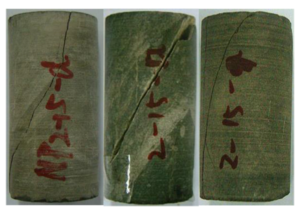 |
Fig. (4). Failure samples in triaxial test. |
3. THE MECHANICAL PROPERTIES OF CLAY-RICH SHALE IN UNLOADING CONDITION
When confining stress is unloaded, the stress state of core samples changes. This influence of unloading on core samples is illustrated in Fig. (5). Because of the unloading (Unloading range is Δσ), lateral bracing decreases, leading to axial stress (σ1) having stronger compressive effect on core samples. This compressive influence will cause the production of new cracks and existing crack propagation [8-9]. It is apparent that these changes of rock structure directly affect rock mechanical property.
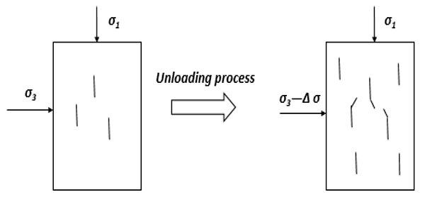 |
Fig. (5). Schematic of influence of unloading on core sample. |
In drilling operation, unloading occurs around wellbore. To illustrate this unloading situation, we take vertical well as an example, illustrated in Fig. (6). Before drilling, stress state in formation is determined by in-situ stress. After drilling, the stress state of rock at the wall of borehole is changed because the rock in borehole was replaced by drilling fluid. In different position at the wall of borehole, the unloading range varies. For instance, unloading range are σh − σr and σH − σr respectively in the position of minimum horizontal stress (σh) and maximum horizontal stress (σH).
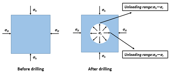 |
Fig. (6). Unloading schematic in vertical well. |
3.1. Experiment Scheme
According to above unloading schematic, triaxial test has been designed to simulate unloading condition so that the influence of unloading on clay-rich shale mechanics can be investigated. For triaxial test, the experiment equipment is shown as Fig. (7). Core sample in triaxial test is placed as Fig. (8) and loaded by 2 principal stresses, i.e., axial stress and confining stress (Fig. 9). The procedure of trixial test is that (1) Confining pressure is loaded by hydraulic oil. (2) Under the same confining pressure, axial stress is loaded to compress core sample to failure. (3) The strain and stress gauge on shale sample give the strain-stress curve of compressive process.
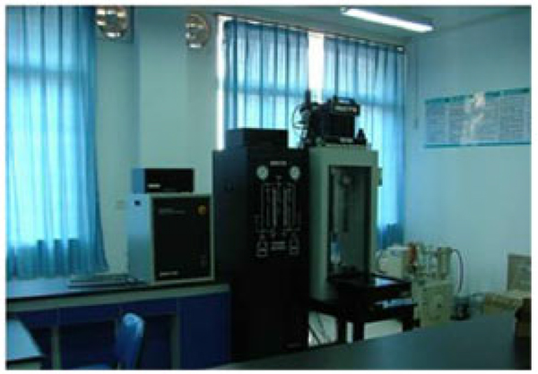 |
Fig. (7). Triaxial test equipment. |
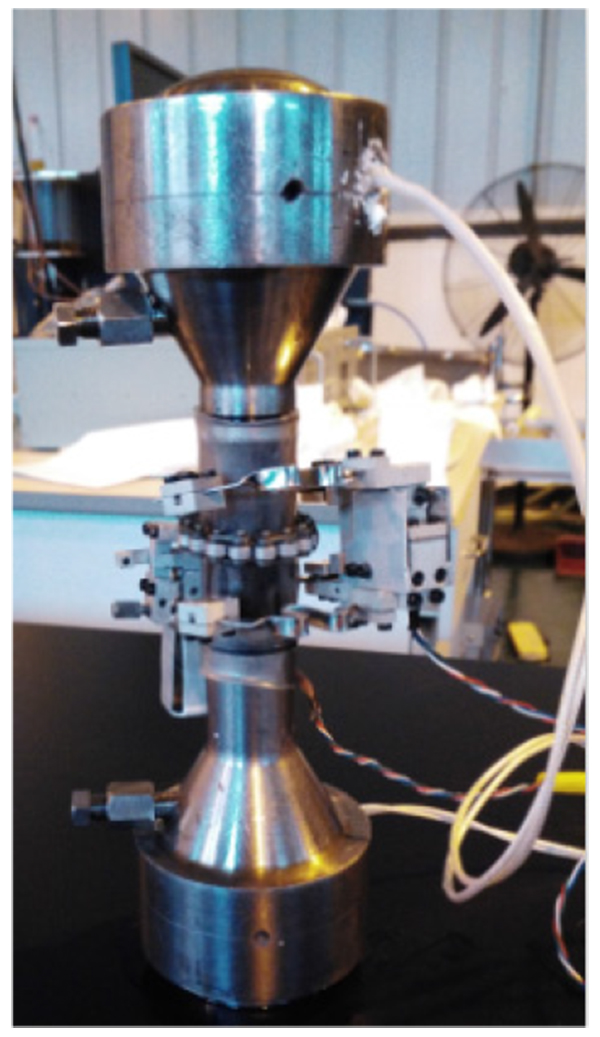 |
Fig. (8). Holder of core sample in triaxial test. |
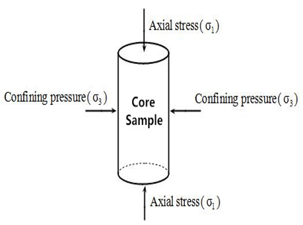 |
Fig. (9). Stress state of core sample in triaxial test. |
For triaxial test in conventional and unloading condition, stress paths of core sample are demonstrated in Fig. (10). In conventional condition, the stress path is that σ3 is firstly loaded to a certain value, then σ1 increases until core sample failures, shown as Fig. (10a). In unloading case (Fig. 10b), the first step is the same that σ3 increases to a constant value. Subsequently, σ1 is loaded to the 80% of triaxial compressive strength (Point K). With the constant σ1, unloading process begins, and σ3 is unloaded from point L to M. When unloading process ends up, σ1 increases again and stops until rock failure. The stress difference between point L and point M is the unloading range. Based on those 2 types of triaxial tests, the shale strength with and without going through unloading can be obtained.
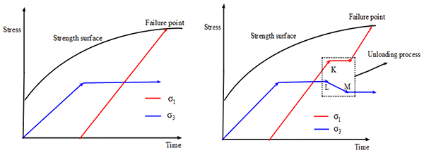 |
Fig. (10). Stress path in triaxial test with unloading and conventional condition. |
3.2. Mechanical Property of Clay-Rich Shale in Unloading Condition
According to the above experimental design, triaxial tests in variable unloading range have been conducted. It can be observed from triaxial tests that stress strain curve in unloading condition has a flat line period, which is unloading phase (Fig. 11). Also note that unloading has no clear impact on failure mode and clay-rich shale samples still maintain single shear failure Fig. (12).
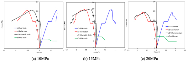 |
Fig. (11). Triaxial stress-strain curves in different unloading range. |
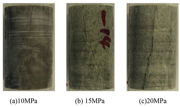 |
Fig. (12). Broken samples in triaxial test with different unloading range. |
Mechanical parameters (cohesion and internal friction angle) can be acquired after performing triaxial test in different confining stress [10]. In term of Mohr-Coulomb criterion, under the different confining stress, Mohr’s cycles in various unloading range are illustrated in Fig. (13). These Mohr’s cycles give the relation between axial stress and confining stress, written as Eq. (1) [11]. Using this relation in Eq. (1), we have acquired mechanical parameters of clay-rich shale in different unloading range, and fitted the relation between unloading range and mechanical parameters, presented in the Fig. (14).
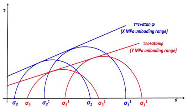 |
Fig. (13). Mohr’s circle with different unloading condition. |
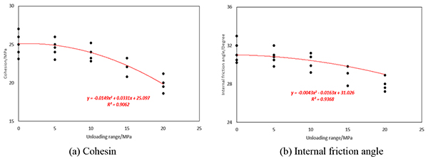 |
Fig. (14). The relation between unloading range and rock mechanic parameters. |
 |
(1) |
Where σ1 is axial stress, MPa. σ3 is confining stress, MPa. C is the cohesion, MPa. φ is the internal friction angle, degree. ζ is the failure angle of clay-rich shale, degree.
Fig. (14) indicates that (1) Cohesion and internal friction angle show similar dropping tendency with unloading range. Both mechanical parameters decrease slowly in the small unloading range. When unloading range is over 10MPa, this dropping rate becomes big. (2) With the same unloading range, cohesion gets larger decline compared to internal friction angle. For instance, when unloading range is 20MPa, the decreasing range of cohesion and internal friction angle are 18.5% and 6.1% respectively. Thus, it can be concluded that unloading has relatively stronger impact on cohesion. (3) Based on experimental data, curve fitting has been performed to establish relation between unloading range and mechanical parameters, written as Eq. (2).
 |
(2) |
Where C(Δσ) is cohesion in different unloading range, MPa. φ(Δσ) is internal friction angle in different unloading range.
4. WELLBORE STABILITY MODEL IN UNLOADING CONDITION
4.1. Stress State in the Wall of Borehole
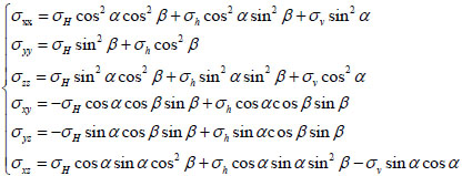
When borehole is un-drilled, stress state of rock around wellbore is only controlled by in-situ stress [12]. Given an arbitrary borehole, through coordinate transformation Fig. (15), in-situ stress components in wellbore coordinate system can be expressed as Eq. (3).
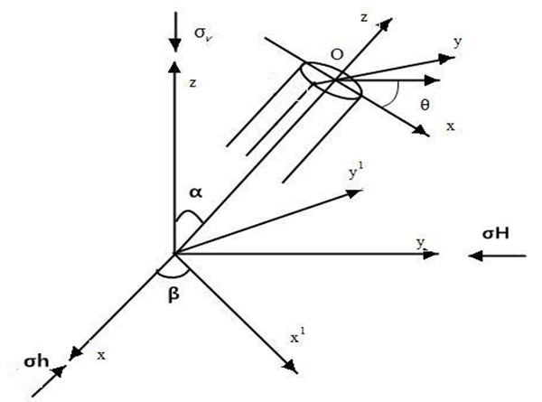 |
Fig. (15). Schematic of coordinate transformation. |
 |
(3) |
Where σxx, σyy, σzz, σxy, σyz, σxz are in situ stress components of the local wellbore coordinates, MPa. σH, σh, σv are maximum horizontal principal, minimum horizontal principal and vertical in-situ stress respectively, MPa. β is the azimuth angle of well, degree. α is the deviation angle of well, degree.
When borehole has been drilled, based on the in-situ stress components in the wellbore coordinate, considering effect from mud pressure, the stress distribution at the wall of borehole can be obtained by a linear superposition, and is written by the following equation:
 |
(4) |
Where K1 is given by:
 |
(5) |
Where σr, σθ, σz are the radial, hoop and axial stress in wellbore coordinate, respectively, MPa. σθz, σrθ, σrz are the three components of shear stress, MPa. θ is wellbore circumferential angle, degree. v is Poisson’s ratio. α1 is Biot coefficient. pi is the mud weight in the wellbore wall, MPa. pp is pore pressure, MPa.
4.2. Unloading Range in the Wall of Borehole
Before drilling operation, for a given point in the wall of borehole (Point P in Fig. (16)), rock is loaded by σxx and σyy in the wellbore plane. By stress decomposition, the stress (σn) along with radial direction of borehole can be expressed as Eq. (6). After drilling, the rock in the borehole is removed and stress along with radial direction of borehole is changed to mud pressure (σr = pi−δϕ(pi − pp)). Therefore, the unloading range along radial direction at the wall of borehole can be given on the basis of σn and mud pressure, shown as Eq. (6). In particular, given the certain well trajectory, the whole distribution of unloading range is illustrated in Fig. (17).
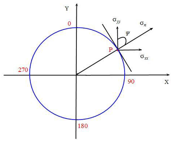 |
Fig. (16). σn in the wellbore plane. |
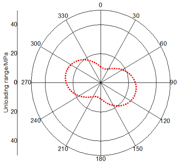 |
Fig. (17). Unloading range distribution in the wall of borehole. |
 |
(6) |
Where σn is the stress along with radial direction, MPa. Δσ is the unloading range, MPa. ϕ is the porosity, %. δ is wellbore permeability coefficient. ψ is included angle between σxx and σn, degree.
4.3. Collapse Pressure in Unloading Condition
Using the stress state around wellbore, we can achieve principal stress at given point in wall of borehole, shown as Eq. (7) [13]. Additionally, the maximum and minimum principal stresses at that point can be obtained by making comparison among these principal stresses. According to principal stresses, considering the influence of unloading on rock strength (Eq.(2)), failure criterion with unloading can be acquired on the basis of Mohr-Coulomb criterion, shown as Eq. (8). The whole computed process of this wellbore stability model is illustrated in Fig. (18).
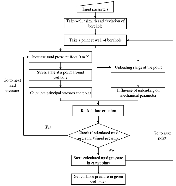 |
Fig. (18). Flow chart of wellbore stability model. |
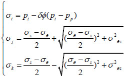 |
(7) |
 |
(8) |
Where σi, σj, σk are principal stresses at one point in the wall of borehole, MPa.
5. THE INFLUENCE OF UNLOADING ON WELLBORE STABILITY
In above presentations, the influence of unloading on clay-rich shale strength has been proved and wellbore stability model was improved to consider unloading impact. In this section, this model was applied to illustrate the influence of unloading on collapse pressure in clay-rich shale formation. The basic input parameters are summarized in Table 3.
| No. | Parameter/unit | Value |
|---|---|---|
| 1 | Porosity/% | 7.6 |
| 2 | Poisson’s ratio | 0.24 |
| 3 | Pore pressure/MPa | 28.8 |
| 4 | Cohesion/MPa | 25.4 |
| 5 | Internal friction angle/degree | 31.3 |
| 6 | Biot coefficient | 0.75 |
5.1. Influence of Unloading in Different Anisotropy of In-Situ Stress
Anisotropy is the characteristic of formation, and especially the anisotropy of in-situ stress has obvious impact on wellbore stability [14]. Hence, to investigate the influence of unloading in variable anisotropy condition, the anisotropy coefficient is defined as ratio of maximum and minimum horizontal principal stress, written as Eq. (9). Take vertical well as an example, minimum horizontal principal stress and vertical stress remains constant (σh = 42MPa σv = 72MPa).With different anisotropy coefficient, the distributions of cohesion and internal friction angle at the wall of borehole are illustrated in Figs. (19 and 20) respectively.
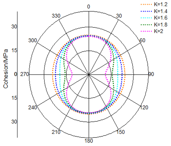 |
Fig. (19). Cohesion of rock in the wall of borehole. |
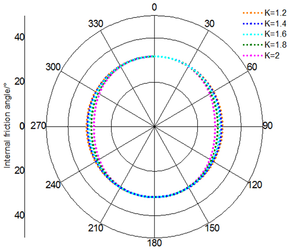 |
Fig. (20). Internal friction angle of rock in wall of borehole. |
 |
(9) |
We can draw the following conclusions from Figs. (17 and 18) that (1) with increasing anisotropy coefficient, this decline of cohesion and internal friction angle are becoming gradually large. (2) Unloading has variable impact on rock strength in different location of borehole. The points with maximum strength decline are in the position of 90 degree and 270 degree circumferential angle. The minimum strength declines occur in the position of 0 degree and 180 degree circumferential angle. (3) In the same unloading condition, cohesion gets larger decrease compared to internal friction angle.
In addition, based on the strength decline caused by unloading, collapse pressures with variable anisotropy coefficient are obtained in conventional and unloading condition, shown in Fig. (21). It can be found out that collapse pressure rises with increasing anisotropy coefficient. Also, in comparison with collapse pressure in conventional condition, collapse pressure in unloading condition is larger. This difference increases with growing of anisotropy coefficient, indicating that unloading has stronger impact on collapse pressure in the formation with high anisotropy coefficient.
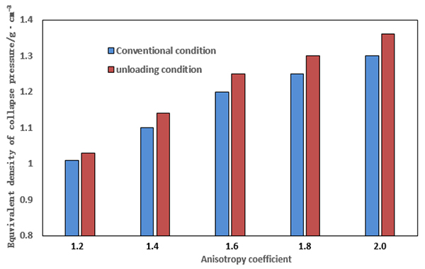 |
Fig. (21). Equivalent density of collapse pressure in different anisotropy coefficient. |
5.2. Influence of Unloading in Different Value of In-Situ Stress
In different geologic situation, the value of in-situ stress is variable. Existing studies have proved that value of in-situ stress is a significant influence factor of collapse pressure [15]. Thus, with the constant anisotropy coefficient (k=1.4) and vertical in-situ stress (σv = 72MPa). Mechanical parameters in different value of in-situ stress are demonstrated in Figs. (22 and 23). It is noticed that mechanical parameters have bigger decline in high value of in-situ stress, and in comparison with cohesion, internal friction angle is less affected by unloading. Besides, strength declined made by unloading is variable around the wall of borehole. The maximum strength decline occurs at 90 degree and 270 degree circumferential angle. In contrast, the points of minimum strength decline are located in 0 degree and 180 degree circumferential angle.
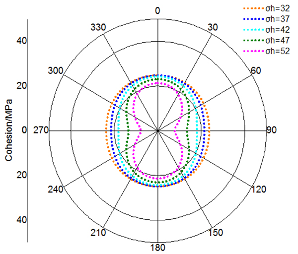 |
Fig. (22). Cohesion of rock in the wall of borehole. |
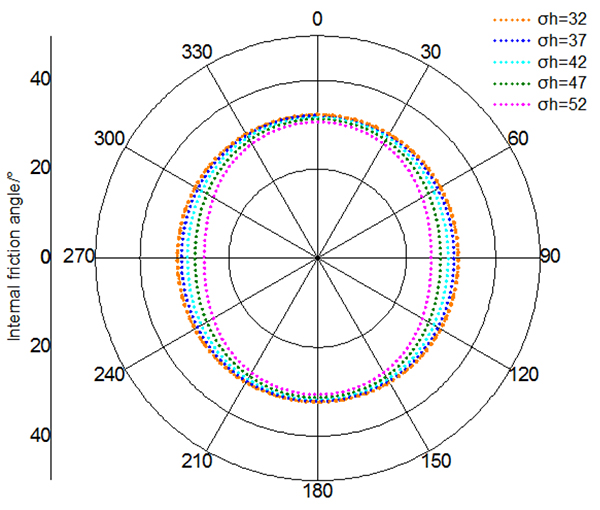 |
Fig. (23). Internal friction angle of rock in wall of borehole. |
Meanwhile, Fig. (24) presents collapse pressures with various value of in-situ stress in conventional and unloading condition. It is shown that safe density is elevated with value of in-situ stress, and unloading causes more increment of collapse pressure. In particular, this increment is larger in high value of in-situ stress, showing that unloading has stronger influence on wellbore stability in high in-situ stress formation.
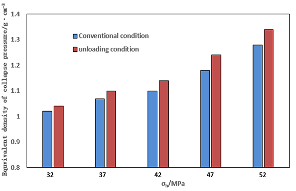 |
Fig. (24). Equivalent density of collapse pressure in different value of in-situ stress. |
5.3. Influence of unloading in different well trajectory
Well trajectory is closely related to wellbore stability. The stress state around wellbore will totally change in different well trajectory, thus leading to distinct unloading situation. Based on the constant in-situ stress (σH = 61, σh = 42, σv=72), considering unloading effect, collapsing pressure in different well track can be illustrated in Fig. (25). The influence of unloading on collapsing pressure is more obvious in azimuths toward minimum horizontal principal in-situ stress (0 degree and 180 degree azimuth), and difference of collapsing pressures between conventional and unloading condition reaches maximum in this azimuth. Also, note that when borehole has low deviation angle (15 degree), the influence of unloading is small, which can be negligible. Whereas, unloading influence become obvious in high deviation angle (75 degree).
6. APPLICATION
As mentioned above, unloading occurs in the beginning of drilling, causing impact on the wellbore stability, especially for determining the initial mud pressure. The model in this paper made an attempt to consider unloading into prediction of initial mud pressure. To verify its practicability, this model has been applied to 6 wells in clay-rich shale formation, Northern China. The drilling loggings of 6 wells show that there is no borehole collapse in the beginning and ratio of well expanding are all less than 12%, which indicate that these initial drilling fluid densities of 6 wells are practical for stabilizing wellbore in clay-rich shale formation. Based on that, wellbore stability model with and without considering unloading are used to predict the collapse pressure, shown as Fig. (26). It demonstrates that conventional model without unloading has clearly lower drilling density, which is not safe for drilling operation. On the contrary, results of model having unloading impact is close agreement with oilfield data and only has average deviation less than 6%, proving its ability of accurately predicting collapse pressure in the initial stage of drilling in clay-rich shale formation. Therefore, this model can be regarded as a viable tool for choosing appropriate initial mud pressure in drilling.
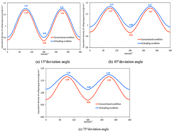 |
Fig. (25). Relation between equivalent density of collapsing pressure and azimuth. |
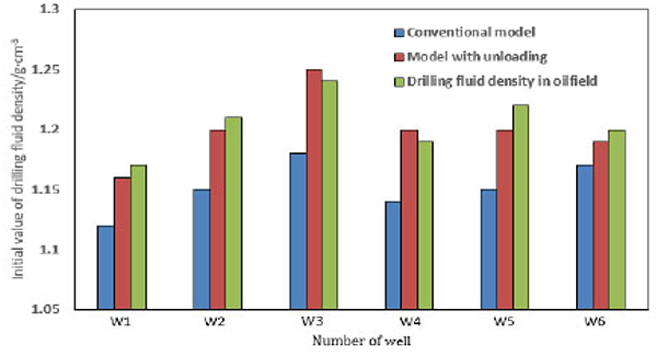 |
Fig. (26). Equivalent density of collapse pressure from different models. |
CONCLUSION
In this paper, to investigate the influence of unloading on wellbore stability, triaxial test has been designed to simulate unloading condition. The triaxial tests, in conventional and unloading condition, indicate that there is no clear influence of unloading on failure mode and clay-rich shale is still single shear failure mode. But unloading can decrease rock strength. With growth of unloading range, decline of mechanical parameters increases. Also the decreasing tendencies of cohesion and internal friction angle are similar, which both decrease slowly in small unloading range, and declines faster when unloading range is over 10MPa. In addition, the decreasing range of internal friction angle is smaller than cohesion, suggesting unloading has relatively stronger effect on cohesion.
During drilling process, stress state around wellbore changes due to unloading. In different in-situ stress condition, influence of unloading varies. In strong anisotropy and high value of in-situ stress, unloading has relatively stronger impact on rock strength, thus causing larger increment of collapse pressure. Meanwhile, well trajectory is associated with unloading effect. With increase of deviation angle, the increment caused by unloading is large and collapsing pressure grows gradually, which means that vertical well is most stable and less affected by unloading. With the constant deviation angle, the difference of collapse pressure in conventional and unloading condition reach peak point in the azimuth toward minimum horizontal principal stress.
In the application, wellbore stability model with and without considering unloading are used to predict the collapse pressure in the beginning of drilling. It is shown that conventional model without unloading impact has clearly lower drilling density, which is not safe for drilling operation. In contrast, results of model considering unloading is close agreement with safe density in oilfield data, indicating its accuracy of predicting collapse pressure. Therefore, it can be a practical tool for determining initial mud pressure in clay-rich shale formation and offer reference for wellbore stability in drilling.
CONSENT FOR PUBLICATION
Not applicable.
CONFLICT OF INTEREST
The authors declare no conflict of interest, financial or otherwise.
ACKNOWLEDGEMENTS
This work is supported by National Natural Science Foundation of China (No. 41772151) and National Science, Technology Major Project of the Ministry of Science and Technology of China(No. 2011ZX05020-007-06) and Application Basic Research Project of Sichuan Province (No. 2014JY0092). Thanks for their supports for this article.


